Showing posts with label Load Balancing. Show all posts

Thursday, 2 July 2026

Mitigating Load Balancer Routing Clamping


In computing and networking, routing clumping (also known as traffic clumping or clustering) refers to the phenomenon where a load balancer or router unevenly sends bursts of traffic to the same backend servers instead of distributing requests evenly across the entire available server pool.

While a load balancer is designed to act as a traffic cop, routing clumping defeats this purpose, momentarily overloading specific servers while leaving others idle.

Primary Causes of Routing Clumping


  • Hashing Bias: Algorithms like 5-tuple hashing (which use source IP, destination IP, ports, and protocols) calculate a fixed value to select a routing path. If thousands of users share a proxy or exit node, the load balancer may calculate the same hash and clump all their traffic onto a single backend server.
  • Sticky Sessions: If you use session persistence (sticky sessions) based on a client's IP, multiple requests from the same office or network range will clump to a single server to maintain session continuity.
  • Connection Multiplexing: Load balancers maintain long-lived backend connections to save resources. When a new batch of requests comes in, the load balancer routes them through existing open connections, causing requests to cluster on specific nodes rather than opening new connections to idle servers.
  • Inconsistent Pod or Instance Count: In environments like Kubernetes, if traffic is processed node-by-node, unequal distribution of application pods across nodes or restrictive node affinities can cause traffic to clump in specific zones or servers.

How to Prevent and Mitigate Clumping


  • Use Round Robin or Least Connections: Switch from IP-hashing or fixed-hash methods to AWS Least Connections or round-robin algorithms, which evaluate server availability in real-time rather than relying on mathematical routing properties.
  • Enable Cross-Zone Load Balancing: For cloud architectures (like AWS Elastic Load Balancing), enabling cross-zone load balancing forces your load balancers to distribute traffic evenly across all registered targets in all enabled Availability Zones.
  • Use Layer 7 Intelligent Routing: Instead of Layer 4 packet forwarding, use a Layer 7 Application Load Balancer to inspect HTTP headers and distribute traffic based on request context, allowing for finer-grained distribution.
  • Deploy Hierarchical Splitting: For massive, hyperscale systems, implementing a hierarchical L4 + L7 structure (ultra-fast L4 hardware balancers routing to a software-based L7 pool) helps prevent clumping while maintaining high raw throughput.


Why round robin routing didn't work well in this scenario so we need to use least connections routing? 


Good question — the answer is about the kind of workload service3 is. Round robin isn't broken in general; it's the wrong fit for this specific traffic shape.

  What each algorithm does 
  • Round robin: hands each new request to the next target in rotation (pod A, B, C, A, B, C…), purely by count — blind to how busy each target currently is.
  • Least outstanding requests (LOR): sends each new request to the target with the fewest in-flight requests right now — i.e., the least-busy one.

Why round robin fails here

Round robin distributes by count, which only equals distributing by load when requests are uniform and short. service3 is the opposite — it has the toxic combination:

1. Highly variable, long service times — a spaCy extraction is anywhere from ~0.3s to multi-second depending on text length/entity count. One heavy request ties a pod up for seconds.
2. Low per-pod concurrency — each pod does ~1–2 concurrent extractions (2 workers, GIL-bound). It saturates almost immediately.

Under those conditions, round robin keeps handing new requests to a pod that's still grinding a heavy multi-second extraction, just because it's "next in rotation" — while a pod that just finished sits idle. The new request then queues head-of-line behind the heavy one for seconds, even though free capacity exists elsewhere. Over a burst this compounds: unlucky pods accumulate a backlog while others drain and idle → exactly the clumping / 33%-CPU-but-3s-latency pattern we measured.

The analogy: round robin is a supermarket sending shoppers to checkout lanes strictly 1‑2‑3‑1‑2‑3, ignoring that lane 2 has someone with a giant cart. You get stuck behind the big cart while lane 3 is empty. LOR is "go to the lane with the fewest items in it right now."

Why LOR fixes it

LOR tracks in-flight requests per target and skips the busy pod — a pod mid-heavy-extraction has a high outstanding count, so new requests go to the idle/draining pods instead. It self-corrects for variance (whichever pod is busy, for any reason, automatically gets fewer new requests until it catches up) and it reaches the idle capacity round robin was stranding.

The catch — why we also needed IP mode

LOR only helps if the ALB is choosing among the right units. In instance mode, the ALB's targets are nodes, so it'd balance outstanding requests across nodes — then kube-proxy randomly picks a pod within the node, re-scrambling the per-pod balance. LOR literally can't see per-pod busyness in instance mode.

IP mode makes the targets pods, so LOR's "least outstanding" is measured per pod → it can actually steer to the least-busy pod. That's why the fix is ip mode + LOR together: ip mode gives LOR the right granularity; LOR gives ip mode the right decision rule. Either alone wouldn't do it.

Two footnotes

- The other 5 services keep round robin — deliberately. auth/data/game/webhook are fast (<0.5s), uniform, high-concurrency — round robin distributes them fine, and there's no reason to touch them. The algorithm choice is workload-specific: LOR for
  slow/variable/expensive backends, round robin for fast/uniform ones.
- Terminology: you said "least connections" — the ALB (L7) equivalent is least outstanding requests, which counts in-flight HTTP requests, not TCP connections. That distinction matters here: the ALB reuses keep-alive connections (one connection carries many sequential requests), so "least connections" would be misleading — LOR counts the actual requests, which is the right signal for this.


In which cases round-robin doesn't help so we need to use least outstanding requests routing?


While Round-Robin works perfectly for uniform traffic and identical servers, it fails when the system experiences variations in request complexity or server capacity. You must switch from Round-Robin to Least Outstanding Requests (LOR) (also known as Least Connections) in the following four specific engineering scenarios:

1. Varying Request Processing Times (Asymmetric Workloads)


  • The Problem: In many applications, some API calls take 5 milliseconds (e.g., fetching a profile cached in memory), while others take 5 seconds (e.g., generating a heavy PDF report or running a complex database query).Why Round-Robin Fails: Round-Robin blindly hands out requests in a strict, alternating sequence. If Server A randomly receives a consecutive string of heavy PDF requests while Server B receives fast cache requests, Server A's queue will spike, causing high latency or timeouts, while Server B sits mostly idle.
  • How LOR Helps: LOR actively tracks the active connection count. It will notice Server A is backed up with pending work and will divert all new incoming traffic to Server B until Server A finishes its heavy processing.

2. Heterogeneous Server Capacities (Mixed Server Sizes)


  • The Problem: Production clusters often use mixed hardware. For example, during an auto-scaling event, you might temporarily mix older 4-core virtual machines with newer, high-performance 16-core instances.Why Round-Robin Fails: Round-Robin treats every backend target as equal. It sends exactly 1,000 requests to the weak 4-core machine and exactly 1,000 requests to the powerful 16-core machine. The weaker machine will quickly choke, run out of memory, or drop packets, while the stronger machine remains underutilised.
  • How LOR Helps: The faster, more powerful server processes and closes connections much quicker than the weaker server. Because its outstanding connection count drops rapidly, LOR naturally funnels a significantly higher volume of traffic to the stronger hardware without needing manual weight configurations.

3. Persistent and Long-Lived Connections (WebSocket & gRPC)


  • The Problem: Modern applications rely heavily on persistent connections like WebSockets, HTTP/2 multiplexing, server-sent events (SSE), or gRPC streams. These connections stay open for minutes or hours.Why Round-Robin Fails: Round-Robin only counts the initial connection establishment. If Server A hosts 50 clients who stay connected for 3 hours chatting, and Server B hosts 50 clients who disconnect after 30 seconds, Round-Robin will continue to feed new connections to both servers equally. Server A will slowly crush under the cumulative weight of long-lived active sessions.
  • How LOR Helps: LOR continuously monitors active, open connections rather than connection arrival rates. It will see that Server A has 50 active outstanding connections and Server B has 0, immediately routing all new clients to Server B.

4. Unpredictable Backend "Cold Starts" and Drifts


The Problem: When a new application container or server boots up (e.g., during a Kubernetes deployment or AWS auto-scaling event), it often suffers from a "cold start" where it runs slowly while warming up caches or compiling code just-in-time (JIT).Why Round-Robin Fails: Round-Robin immediately floods the newly booted server with its full share of production traffic. Because the server is not yet performing at 100% capacity, this sudden burst easily overwhelms it, causing it to crash immediately after launching.
How LOR Helps: LOR naturally throttles traffic to the warming server. Since the cold server processes its first few requests slowly, its outstanding request count will naturally rise, signaling the load balancer to back off and route traffic elsewhere until the server catches up.


Algorithm Comparison Table


  • Scenario
  • Round-Robin Behavior
  • Least Outstanding Requests Behavior
  • All requests take equal time 
  • Perfect, completely equal distribution.
  • Excellent, identical result to Round-Robin.
  • Mix of short & long requests
  • Overloads random servers (creates traffic clumps).
  • Dynamically balances the processing queue.
  • Mixed server capacities
  • Overwhelms smaller, weaker backend servers.
  • Directs more traffic to faster instances automatically.
  • Long-lived WebSockets / gRPC
  • Ignores session duration; causes massive load imbalance.
  • Tracks real-time active sessions perfectly.

If you are using a cloud platform, you can learn more about implementing this via the AWS Least Outstanding Requests Documentation or the NGINX Least Connections Guide.


k8s ingress - AWS ALB


To implement Least Outstanding Requests (LOR) routing with an AWS Application Load Balancer (ALB) inside a Kubernetes cluster, you must configure it using the AWS Load Balancer Controller.

By default, the AWS ALB uses Round-Robin routing. You can change this behavior by applying a specific routing annotation to your Kubernetes TargetGroupBinding or Ingress resource.


1. Ingress Configuration Example


Apply the alb.ingress.kubernetes.io/target-group-attributes annotation to your Ingress manifest. This tells the AWS controller to configure the underlying target groups to use the load_balancing.algorithm.type=least_outstanding_requests setting.

apiVersion: networking.k8s.io/v1
kind: Ingress
metadata:
  name: my-app-ingress
  namespace: production
  annotations:
    # Essential ALB Controller configurations
    kubernetes.io/ingress.class: alb
    alb.ingress.kubernetes.io/scheme: internet-facing
    alb.ingress.kubernetes.io/target-type: ip
    
    # Enable Least Outstanding Requests Routing
    alb.ingress.kubernetes.io/target-group-attributes: load_balancing.algorithm.type=least_outstanding_requests
spec:
  rules:
    - http:
        paths:
          - path: /
            pathType: Prefix
            backend:
              service:
                name: my-app-service
                port:
                  number: 80


2. Crucial Step: Use "IP" Target Type


When running AWS ALB in Kubernetes, you should always set alb.ingress.kubernetes.io/target-type: ip instead of instance mode. 

  • Why? In instance mode, the ALB routes traffic to NodePorts on the EC2 worker nodes. The node then uses kube-proxy (iptables or IPVS) to randomly route the packet to a pod. This completely breaks the math behind Least Outstanding Requests because the ALB can only see outstanding connections to the node, not the actual pods.
  • The Fix: Using ip mode configures the ALB to bypass the node network entirely and route traffic directly to the Pod IPs. This gives the ALB true visibility into the exact outstanding request count for each application container.

3. Verify the Configuration


After applying the manifest via kubectl apply -f ingress.yaml, you can verify the changes are active in AWS:
  • Open the AWS EC2 Console and navigate to Target Groups.
  • Select the target group automatically generated by your Kubernetes Ingress.
  • Click on the Attributes tab.
  • Verify that Routing algorithm is set to Least outstanding requests.

Alternatively, check the AWS Load Balancer Controller logs to ensure the modification was successfully reconciled:

kubectl logs -n kube-system deployment/aws-load-balancer-controller

---

Thursday, 25 June 2026

AWS EC2: Application Load Balancer


An Application Load Balancer (ALB) is a fully managed AWS service that automatically distributes incoming HTTP and HTTPS traffic across multiple backend targets.

It operates at the Application Layer (Layer 7) of the Open Systems Interconnection (OSI) model.

Key Features:

  • Content-Based Routing: Routes traffic based on URL paths (/api vs /images) or hostnames (://example.com).
  • Container Support: Integrates directly with Amazon ECS and EKS using dynamic port mapping.
  • Advanced Protocols: Native support for modern protocols like HTTP/2, gRPC, and WebSockets.
  • Security Integration: Features built-in HTTPS/TLS termination and integrates directly with AWS WAF for web security.

How Components Work Together


  • Listener: Evaluates connection requests from clients using protocols and ports you configure.
  • Rules: Determines how the load balancer routes requests to its registered targets.
  • Target Group: Groups backend resources (like EC2 instances, containers, or IP addresses) that receive the traffic

How ALB health checks keep applications online?


An Application Load Balancer (ALB) keeps your application online by continuously monitoring the health of your backend targets and dynamically redirecting traffic away from failing nodes.

1. Automatic Traffic Redirection


The ALB sends periodic ping requests (health checks) to every registered target. If a target fails to respond correctly, the ALB marks it as unhealthy and immediately stops sending user traffic to it. Traffic is rerouted to the remaining healthy nodes with zero downtime for the user.

2. Auto Scaling Integration


When paired with an Auto Scaling Group (ASG), ALB health checks can trigger the automatic replacement of broken instances.
  • The Problem: An EC2 instance might be running (healthy at the hardware level), but the web server inside it has crashed (unhealthy at the application level).
  • The Solution: The ALB tells the ASG that the instance is failing application health checks. The ASG terminates that specific broken instance and launches a fresh, working one.

3. Graceful Recovery


When an unhealthy instance recovers, or when a new instance is launched, the ALB does not send traffic to it immediately. It enters an initial state and undergoes consecutive successful health checks. Only when it passes the threshold does the ALB safely introduce it back into the traffic rotation.

How to Configure an ALB Health Check


You configure health checks inside the Target Group settings using these parameters:

Parameter                  What it does                                                                          Recommended Setting
========                   =========                                                                           =================
Health Check Path     The URL endpoint the ALB hits 
                                      (e.g., /health or /index.html).                                                    /health
Healthy Threshold      Consecutive successes needed to mark a target as healthy.      3
Unhealthy Threshold  Consecutive failures needed to mark a target as unhealthy.     2
Timeout                        How long the ALB waits for a response before failing.           5 seconds
Interval                         The time between individual health check pings.                    30 seconds
Success Codes              The HTTP status codes that prove the app is working.            200 (or 200-399)


When you configure an ALB, you do not select an Availability Zone (AZ) directly; instead, you must select at least two subnets in different Availability Zones to ensure high availability.

  • How it works: AWS places a load balancer node in each of the specified subnets.
  • The AZ link: Because each subnet belongs to exactly one AZ, this fundamentally binds the ALB's nodes to those corresponding Availability Zones.
  • Custom routing: You can modify the subnets via the Update Availability Zones settings in the EC2 Console at any time.

Public ALB


Binding an ALB to public subnets makes it a public (internet-facing) load balancer. 

When you create an internet-facing ALB, AWS requires you to select public subnets so the ALB nodes can receive a public IP address and route traffic from the internet.

Key Characteristics:

  • Public DNS: The ALB receives a public DNS name that resolves to public IP addresses.
  • Internet Gateway: The selected public subnets must have a route to an Internet Gateway (IGW) in their route tables.
  • Target Routing: Even though the ALB is public, it can still route traffic to EC2 instances living in private subnets
An internet-facing ALB routes traffic directly to the individual backend targets (such as EC2 instances or IP addresses), not to the private subnets themselves.


How Routing Works

  • Target Group Config: You configure the ALB to route traffic to a Target Group.
  • Direct Node Communication: The ALB nodes in the public subnets communicate directly with the private IP addresses of your backend nodes.
  • Cross-Subnet Traffic: AWS handles this routing internally via the VPC router, allowing the public ALB to securely traverse into private subnets.

Configuration Checklist

  • VPC: Both the public subnets (where the ALB lives) and the private subnets (where the nodes live) must be in the same VPC.
  • Security Groups: The private instances must have a security group that allows inbound traffic from the ALB's security group


Private ALB


An internal (private) ALB routes traffic in the exact same way as a public ALB, but it is only accessible within your VPC or connected networks.

It routes traffic directly to individual backend targets, not to subnets.

Key Characteristics

  • Private Subnets: You deploy the ALB nodes into private subnets.
  • Private DNS: The ALB receives a public DNS name, but it resolves exclusively to private IP addresses.
  • No Internet Access: It cannot receive any traffic from the public internet because it lacks a public IP.

Common Use Cases

  • Internal Microservices: Routing traffic from a public-facing web tier to a private backend API tier.
  • Hybrid Networks: Routing traffic coming from an on-premises data centre via AWS Direct Connect or a VPN

Setting Up ALB in AWS Console


AWS Elastic Load Balancing shows basic building blocks of AWS Load Balancer which include listeners and target groups. 

To create Application Load Balancer go to EC2 >> Load balancers >> Create Load balancer >> Select load balancer type (click on Create under Application Load Balancer)


Here we can set:

  • Basic configuration
    • Name
    • Scheme (cannot be changed after the load balancer is created)
      • Internet-facing. An internet-facing load balancer routes requests from clients over the internet to targets. Requires a public subnet. 
      • Internal. An internal load balancer routes requests from clients to targets using private IP addresses.
    • IP address type. Select the type of IP addresses that your subnets use.
      • IPv4. Recommended for internal load balancers.
      • Dualstack. Includes IPv4 and IPv6 addresses.
  • Network mapping. The load balancer routes traffic to targets in the selected subnets, and in accordance with your IP address settings.
    • VPC. Virtual private cloud for your targets. If balancer is internet-facing, only VPCs with an internet gateway are enabled for selection. The selected VPC cannot be changed after the load balancer is created. As VPC is region-specific so is Application Load Balancer.
    • Mappings. Once VPC is selected, its availability zones are listed here and are selectable. Select at least two Availability Zones and one subnet per zone. The load balancer routes traffic to targets in these Availability Zones only. Availability Zones that are not supported by the load balancer or the VPC are not available for selection. We should select all AZs that we listed in the Auto scaling group (if we used it).
  • Security groups. A security group is a set of firewall rules that control the traffic to your load balancer. We can select up to 10 security groups.
    • If our application is listening for HTTP requests on port 80 we should select a security group with:
      • Inbound rule: accept HTTP/TCP traffic on port 80 with source Anywhere-IPv4
      • Outbound rule: allow all traffic for all protocols and port ranges to custom destination 0.0.0.0/0
  • Listeners and routing. A listener is a process that checks for connection requests using the port and protocol you configure. The rules that you define for a listener determine how the load balancer routes requests to its registered targets.
    • Add listener
      • Protocol e.g. HTTP
      • Port e.g. 80. This is a public facing port and it does not need to be the same as the port from the attached target group. E.g. LB can listen on port 80 and forward traffic to target group port 8080.
      • Default action: Forward to (select a target group)
      • Add listener tags
  • Add-on services - optional
    • AWS Global Accelerator
  • Tags - optional


More info on Scheme, from AWS documentation:

When you create a load balancer, you must choose whether to make it an internal load balancer or an internet-facing load balancer.

The nodes of an internet-facing load balancer have public IP addresses.

The nodes of an internal load balancer have only private IP addresses.

Both internet-facing and internal load balancers route requests to your targets using private IP addresses. Therefore, your targets do not need public IP addresses to receive requests from an internal or an internet-facing load balancer.

More info on how ALB routes traffic to multiple Availability Zones (and about what Load Balancer Nodes are):

When you enable an Availability Zone for your load balancer, Elastic Load Balancing creates a load balancer node in the Availability Zone. 

The nodes for your load balancer distribute requests from clients to registered targets. When cross-zone load balancing is enabled, each load balancer node distributes traffic across the registered targets in all enabled Availability Zones. When cross-zone load balancing is disabled, each load balancer node distributes traffic only across the registered targets in its Availability Zone.

Before a client sends a request to your load balancer, it resolves the load balancer's domain name using a Domain Name System (DNS) server. The DNS entry is controlled by Amazon, because your load balancers are in the amazonaws.com domain. The Amazon DNS servers return one or more IP addresses to the client. These are the IP addresses of the load balancer nodes for your load balancer.

As traffic to your application changes over time, Elastic Load Balancing scales your load balancer and updates the DNS entry. The DNS entry also specifies the time-to-live (TTL) of 60 seconds. This helps ensure that the IP addresses can be remapped quickly in response to changing traffic.

The client determines which IP address to use to send requests to the load balancer. The load balancer node that receives the request selects a healthy registered target and sends the request to the target using its private IP address.

With Application Load Balancers, the load balancer node that receives the request uses the following process:

1) Evaluates the listener rules in priority order to determine which rule to apply.

2) Selects a target from the target group for the rule action, using the routing algorithm configured for the target group. The default routing algorithm is round robin. Routing is performed independently for each target group, even when a target is registered with multiple target groups.

For further info: How Elastic Load Balancing works - Elastic Load Balancing

ALB nodes use Elastic Network Interface (Elastic network interfaces - Amazon Elastic Compute Cloud) which has public IP address:

At least one ENI is created and attached to the balancer in each availability zone where the balancer is deployed (except NLB, which should only have one per AZ). Over the life of the balancer, new ENIs will appear and old ones will disappear, as the balancer scales horizontally (number of nodes) and/or vertically (capacity of underlying hardware), all of which is handled transparently by the infrastructure. Even though you can tag them, the tagging will become stale over time.

Source: amazon web services - AWS - Affect Load Balancer's tags to its Network Interfaces (ENI) - Stack Overflow


You can determine the IP addresses associated with an internal load balancer or an internet-facing load balancer by resolving the DNS name of the load balancer. These are the IP addresses where the clients should send the requests that are destined for the load balancer. However, Classic Load Balancers and Application Load Balancers use the private IP addresses associated with their elastic network interfaces as the source IP address for requests forwarded to your web servers.

Source: Find the IP address used by a load balancer to forward traffic to web servers


Load balancer routes requests to the targets in a target group and performs health checks on the targets. Target group is accepting requests from the load balancer and forwards them to targets. These targets can be e.g. EC2 instances created either manually or through auto scaling group.

How to create a Target Group used by Load Balancer listeners? (This applies for any type of Load Balancer)

EC2 >> Target groups >> Create target group

Step 1: Specify group details


Here we can set:

  • Basic configuration. Settings in this section cannot be changed after the target group is created.
    • Target type
      • Instances
        • Supports load balancing to instances within a specific VPC.
        • Facilitates the use of Amazon EC2 Auto Scaling  to manage and scale your EC2 capacity.
      • IP addresses
        • Supports load balancing to VPC and on-premises resources.
        • Facilitates routing to multiple IP addresses and network interfaces on the same instance.
        • Offers flexibility with microservice based architectures, simplifying inter-application communication.
        •  Supports IPv6 targets, enabling end-to-end IPv6 communication, and IPv4-to-IPv6 NAT.
      • Lambda function
        • Facilitates routing to a single Lambda function.
        •  Accessible to Application Load Balancers only.
      • Application Load Balancer
        • Offers the flexibility for a Network Load Balancer to accept and route TCP requests within a specific VPC
        • Facilitates using static IP addresses and PrivateLink with an Application Load Balancer.
    • Target group name
    • Protocol:Port e.g. If our application is accepting HTTP requests on port 8080 this would be HTTP:8080
    • VPC - VPC with the instances that you want to include in the target group.
    • Protocol version
      • HTTP1. Send requests to targets using HTTP/1.1. Supported when the request protocol is HTTP/1.1 or HTTP/2.
      • HTTP2. Send requests to targets using HTTP/2. Supported when the request protocol is HTTP/2 or gRPC, but gRPC-specific features are not available.
      • gRPC. Send requests to targets using gRPC. Supported when the request protocol is gRPC.
  • Health checks. The associated load balancer periodically sends requests, per the settings below, to the registered targets to test their status.
    • Health check protocol
      • HTTP
      • HTTPS
    • Health check path. Use the default path of “/“ to ping the root, or specify a custom path if preferred.
    • Advanced health check settings
      • Port. The port the load balancer uses when performing health checks on targets. The default is the port on which each target receives traffic from the load balancer, but you can specify a different port.
        • Traffic port
        • Override
      • Healthy threshold. The number of consecutive health checks successes required before considering an unhealthy target healthy.
      • Unhealthy threshold. The number of consecutive health check failures required before considering a target unhealthy.
      • Timeout. The amount of time, in seconds, during which no response means a failed health check.
      • Interval. The approximate amount of time between health checks of an individual target
      • Success codes. The HTTP codes to use when checking for a successful response from a target. You can specify multiple values (for example, "200,202") or a range of values (for example, "200-299").
  • Attributes
  • Tags - optional


Step 2: Register targets

This is an optional step to create a target group. However, to ensure that your load balancer routes traffic to this target group you must register your targets.


After load balancer is created it takes several minutes while it's in provisioning state and get into active state. After this, we can use its DNS name in order to see what it's doing.

If we copy its DNS name and paste it to our browser, if we haven't registered any targets in the target group associated with the load balancer, we'll get error 503 - Service Temporary Unavailable.

If we've registered targets and are getting error 504 Gateway time-out, we should check first if security groups (firewalls) for our EC2 instances (inbound rule - source IP range) are set up correctly as this error usually indicates that inbound traffic is not allowed.

AWS Terraform provider offers provisioning all these resources:

 
How is AWS Application Load Balancing usually implemented?
 
Let's say we have our application running on 3 EC2 instances where 2 are in the same region e.g. us-west-2 but in separate availability zones e.g. us-west-2a and us-west-2b. Third EC2 instance is in eu-central-1, in availability zone eu-central-1a.
 
VPC is region-specific but can span multiple availability zones (AZ). 
Subnet is an IP address range within VPC.
VPC can have public and private subnets.
VPC can be divided into multiple subnets but each subnet is AZ-specific.
AZ can have multiple subnets.

So, all EC2 instances belong to the same VPC but, as they are in different AZs, each of them belongs to different subnet.
 
Load balancer must be in the public subnet of VPC as clients communicate with load balancer via internet (public network).
 
Load balancer does not get associated directly with EC2 instances but subnets:

resource "aws_lb" "test" {
    subnets = ["subnet-0001", "subnet-0002"] 
    ...
}

Target group is associated with VPC:
 
resource "aws_alb_target_group" "test" {
    vpc_id   = var.vpc_id
    ...
}


Difference between ALB and NLB (Network Load Balancer)


An Application Load Balancer (ALB) and a Network Load Balancer (NLB) serve different purposes based on the layer of the network they operate on and the type of traffic they handle.

The core difference is that an ALB understands application-level traffic (Layer 7) like HTTP/HTTPS headers, while an NLB handles low-level network traffic (Layer 4) like TCP/UDP packets at extreme speeds.

Direct Comparison Matrix


Feature          Application Load Balancer (ALB)                     Network Load Balancer (NLB)
======         =========================                      =======================
OSI Layer     Layer 7 (Application)                                            Layer 4 (Transport)
Protocols       HTTP, HTTPS, HTTP/2, gRPC, WebSockets      TCP, UDP, TLS
IP Addresses 
                       Dynamic IPs (Changes automatically; requires a DNS name)  
                                                                                                     Static IPs (Can assign an Elastic IP per AZ)
Routing Features  
                        Advanced (Path, Host, Query parameters, Headers)  
                                                                                                      Basic (Port and IP protocol routing only)
Performance  
                        Optimized for complex web apps (Millions of requests/sec)  
                                                                                                      Optimized for ultra-low latency (Billions of requests/sec)


Key Technical Differences


1. Smart Routing vs. Raw Speed


  • ALB (Smart): Can read the contents of your HTTP requests. It can route traffic bound for ://example.com to an API server cluster, and traffic for ://example.com to a storage cluster.
  • NLB (Fast): Does not look inside the data packet. It simply looks at the target port and forwards the packet instantly. This results in ultra-low latency (measured in milliseconds).

2. IP Addresses and DNS


  • ALB: Scale out dynamically by adding or removing nodes. This causes its underlying IP addresses to change frequently. You must always point your domain name to the ALB's DNS Name, never to a static IP.
  • NLB: Gives you a Static IP address per Availability Zone. You can also assign your own Elastic IP addresses. This is critical if your corporate clients need to whitelist specific, unchanging IPs in their firewalls.

3. Client IP Preservation


  • ALB: Terminates the connection and makes a new one to your backend instances. The backend see the ALB's private IP. To find the real user's IP, your code must read the X-Forwarded-For HTTP header.
  • NLB: Passes the original TCP packet straight through to your backend server. Your backend instances see the original source IP address of the client natively, without needing extra headers.


When to Choose Which?


Choose an ALB if you are building:
  • Standard web applications and microservices.
  • Containerized apps (ECS/EKS) requiring path-based or host-based routing.
  • Applications requiring tight integration with AWS Web Application Firewall (WAF).

Choose an NLB if you are building:
  • Non-HTTP applications (e.g., gaming servers, SFTP, MQTT, database clusters).
  • Architectures requiring fixed, static IP addresses or Elastic IPs.
  • High-frequency financial applications where sub-millisecond network latency is a hard requirement

Which alerts should typically be set for AWS ALB?


To keep your applications highly available, you should set up Amazon CloudWatch alarms for a mix of availability, performance, and target health metrics.

The most critical metrics to monitor for an AWS ALB are grouped by priority below:

1. High Priority (Critical Infrastructure Impact)

UnHealthyHostCount (Per Target Group)
What it means: The number of backend instances failing health checks Target Group Metrics.
Alert Threshold: > 0 (or > 1 for larger clusters).
Why it matters: Signals that your servers are crashing or cannot handle traffic.

HTTPCode_Target_5XX_Count
What it means: The number of 5xx server error codes generated by your backend application ALB Metrics.
Alert Threshold: Depends on baseline traffic, typically > 5 failures within a 1-minute to 5-minute window.
Why it matters: Indicates server crashes, database connection timeouts, or unhandled exceptions in your application code.

HTTPCode_ELB_5XX_Count
What it means: The number of 5xx errors generated directly by the ALB itself (not your servers) ALB Metrics.
Alert Threshold: > 0.
Why it matters: Usually means the ALB cannot find any healthy hosts, or it is experiencing a configuration mismatch (e.g., bad TLS handshake with the target).

2. Medium Priority (Performance & User Experience)

TargetResponseTime
What it means: The time elapsed (in seconds) from when the ALB sent the request to the target until the target started responding ALB Metrics.
Alert Threshold: Use the p95 or p99 statistic. Alert if it exceeds your application’s maximum acceptable latency (e.g., > 2.0 seconds).
Why it matters: Users are experiencing severe application slowdowns, likely due to high CPU/memory usage on your instances.

RejectedConnectionCount
What it means: The load balancer is rejecting connections because it has reached its maximum capacity ALB Metrics.
Alert Threshold: > 0.
Why it matters: Your application is getting sudden traffic spikes and the ALB cannot scale fast enough, or backend targets are failing to keep up.

3. Low Priority (Anomalies & Security)

HTTPCode_Target_4XX_Count
What it means: The number of 4xx client errors (like 404 Not Found or 401 Unauthorized) returned by backend targets ALB Metrics.
Alert Threshold: A significant spike above your standard baseline.
Why it matters: A sudden surge might indicate a broken frontend deployment, a bad API update, or a malicious entity scanning your network for vulnerabilities.

Summary Checklist for CloudWatch Alarms

Metric Name                               Statistic         Recommended       Suggested                      Action
                                                                            Period                     Threshold     
==========                              ======          ===========       ========                     =====
UnHealthyHostCount                    Maximum   1 Minute                         > 0                          Page/On-Call
HTTPCode_ELB_5XX_Count     Sum             1 Minute                         > 0                          Page/On-Call
HTTPCode_Target_5XX_Count  Sum            5 Minutes                > 10 (or > 1% of traffic) Ticket/Slack
TargetResponseTime                     p95              5 Minutes> [Your Limit]                                Ticket/Slack


Resources:


Thursday, 8 August 2024

Load Balancing Algorithms

Load balancing:
  • Used in distributed systems to distribute incoming network traffic across multiple servers or resources
  • Crucial for optimizing performance and ensuring even distribution of workload
  • Enhances system reliability by ensuring no single server becomes a bottleneck, thus reducing the risk of server overload and potential downtime


image source: Post | LinkedIn


Some popular load balancing algorithms:

  • Round Robin
    • distributes incoming requests sequentially to each server in a circular manner
    • simple and easy to implement but may not take into account server load or capacity
    • most used
  • Weighted Round Robin
    • similar to Round Robin, but with the ability to assign different weights to servers based on their capacity or performance
    • Servers with higher weights receive more requests
  • IP Hash
    • Uses the client's IP address to determine which server to send the request to
    • Requests from the same IP address are consistently routed to the same server
  • Least Connections
    • directs incoming requests to the server with the fewest active connections at the time
    • helps distribute the load evenly among servers based on their current workload
  • Least Response Time
    • Routes requests to the server with the lowest response time or latency
    • Aims to optimize performance by sending requests to the fastest server.
  • Random
    • Randomly selects a server from the pool to handle each request
    • While simple, it may not ensure even distribution of load across servers

Each load balancing algorithm has its own advantages and considerations.
The choice of algorithm depends on the specific requirements of the system and the desired load distribution strategy.


Disclaimer:

All credits for the inspiration for the article, an infograph image and part of the content go to Sina Riyahi [https://www.linkedin.com/in/sina-riyahi/].

Saturday, 6 July 2024

Google Cloud Load Balancing


Virtual machines autoscaling solves the issue of availability during the high load period and also cost optimization during the low load by scaling up and down in respond to changing loads. 

Why do we need Load Balancers?


Cloud Load Balancing allows our customers get to our application when it might be provided by four VMs one moment, and by 40 VMs at another. The job of a load balancer is to distribute user traffic across multiple instances of an application. By spreading the load, load balancing reduces the risk that applications experience performance issues

source: Cloud Load Balancing overview  |  Google Cloud


Cloud Load Balancing 


Cloud Load Balancing:
  • Fully distributed
  • Software-defined
  • Managed service for all our traffic
  • Load balancers don’t run in VMs that we have to manage so we don’t have to worry about scaling or managing them. 
  • Can be put it in front of all of our traffic:
    • HTTP or HTTPS
    • TCP 
    • SSL traffic
    • UDP traffic 
  • Provides cross-region load balancing (remember that Google Cloud VPCs are cross-regional), including automatic multi-region failover, which gently moves traffic in fractions if backends become unhealthy
  • Reacts quickly to changes in users, traffic, network, backend health, and other related conditions
  • Doesn't require so-called “pre-warming”
    • If we anticipate a huge spike in demand, for example our online game is already a hit, we don't need to file a support ticket to warn Google of the incoming load. 

Load Balancing Types


Depending on at which OSI level they operate, Cloud Load Balancers can be divided into two types:
  • Application Load Balancers
    • Layer 7 load balancer for our applications with HTTP(S) traffic
  • Network Load Balancers
    • Layer 4 load balancers that can handle TCP, UDP, or other IP protocol traffic

Depending where the traffic is coming from, Load Balancers can be dived into two types:
  • External Load Balancers
    • For traffic coming into the Google network from the Internet
  • Internal Load Balancers
    • Accepts traffic on a Google Cloud internal IP address and load balances it across Compute Engine VMs
    • If we want to load balance traffic inside our project, say, between the presentation layer and the business layer of our application

Application Load Balancers


Layer 7 load balancer for our applications with HTTP(S) traffic.

Depending on whether our application is internet-facing or internal they can be deployed as:
  • External Application Load Balancers - intended for traffic coming into the Google network from the Internet
    • Global HTTP(S) load balancer - if we need cross-regional load balancing for a web application
    • Regional External Application load balancer
  • Internal Application Load Balancers, which can be deployed as:
    • Cross-region Internal Application Load Balancers - support backends in multiple regions and are always globally accessible. Clients from any Google Cloud region can send traffic to the load balancer. Balance traffic to backend services that are globally distributed, including traffic management that ensures traffic is directed to the closest backend.
    • Regional Internal Application Load Balancers - support backends only in a single region
source: Cloud Load Balancing overview  |  Google Cloud


Network Load Balancers


Layer 4 load balancers that can handle TCP, UDP, or other IP protocol traffic. 
Available as:
  • Proxy Network Load Balancers 
  • Passthrough Network Load Balancers

Proxy Network Load Balancers 

  • Support TLS offloading
  • Depending on whether your application is internet-facing or internal, they can be deployed as:
    • External Proxy Network Load Balancers
      • Global External Proxy Network Load Balancers - support backends in multiple regions
        • Global SSL Proxy load balancer - For Secure Sockets Layer traffic that is not HTTP. This proxy service only works for specific port numbers, and only for TCP
        • Global TCP Proxy load balancer - If it’s other TCP traffic that doesn’t use SSL. This proxy service only works for specific port numbers, and only for TCP
      • Regional External Proxy Network Load Balancers - support backends in a single region
      • Classic Proxy Network Load Balancers - global in Premium Tier but can be configured to be effectively regional in Standard Tier
    • Internal Proxy Network Load Balancers 
      • Regional Internal Proxy Network Load Balancers

source: Cloud Load Balancing overview  |  Google Cloud


Passthrough Network Load Balancers

  • support for IP protocols such as UDP, ESP, and ICMP
  • Can be:
    • External Passthrough Network Load Balancers
      • Regional External Passthrough Network load balancer - If we want to load balance UDP traffic, or traffic on any port number, we can use it to load balance across a Google Cloud region
    • Internal Passthrough Network Load Balancers
      • Regional Internal Passthrough Network Load Balancers

source: Cloud Load Balancing overview  |  Google Cloud


How to choose the right Load Balancer?


source: source: Cloud Load Balancing overview  |  Google Cloud

Saturday, 1 June 2024

Deploying Microservices Application on the AWS EKS with AWS Console and kubectl


Introduction


One of my previous articles, Deploying Microservices Application on the Minikube Kubernetes cluster | My Public Notepad, shows how to use kubectl to deploy a microservices application (Cats/Dogs Voting application) onto a single-node cluster which runs in VM on the local machine and which is created by Minikube.

In Provisioning multi-node cluster on the local machine using Kubeadm and Vagrant | My Public Notepad it is discussed how to use Vagrant to launch multiple VMs on the local machine, each of them hosting a node from the multi-node cluster created and managed by Kubeadm. 

The next example would be using Kubeadm to provision multi-node cluster running on multiple bare-metal machines and then using kubectl to deploy a microservices application on that cluster. That will be a topic for one of my future articles but today I want to share my experience with using AWS Console to provision a multi-node cluster in Amazon Elastic Kubernetes Service (EKS) and then kubectl to deploy a microservices application (Cats/Dogs Voting application) onto it. 


I will try to maximise use of AWS Free Tier but note that this setup will incur some charges and therefore make sure you destroy chargeable resources (I'll list them down in the article) as soon as successfully complete the test of the application deployment.

Prerequisites:

  • AWS:
    • An account is created
    • IAM User that kubectl will be using to authenticate to AWS. As I'm planning later to use Terraform to provison the infrastructure for a similar demo, I created IAM user named terraform but in this article we won't be using Terraform at all and this user name can be any arbitrary name.
  • Local machine:
    • AWS CLI is installed and configured
    • kubectl is installed

Creating a cluster in EKS Dashboard in AWS Console 


We'll perform the following steps in order to create an EKS cluster:
  • create IAM role for cluster
  • create a cluster
  • crate IAM role for (worker) nodes
  • create (worker) node group

This is how looks the main EKS page:


As Getting started with Amazon EKS – AWS Management Console and AWS CLI - Amazon EKS and Amazon EKS cluster IAM role - Amazon EKS describe, before we create a cluster we need to create an IAM Role which needs to have these two policies attached:

1) AmazonEKSServicePolicy - AWS Managed Policy - defines permissions of this role (what resources can access anyone who assumes this role)
2) trust policy (which defines who can assume/take this role). Role needs to have this piece of information attached to it as if anyone could assume it, that would defeat the purpose of roles. We want to allow EKS service to assume it so this policy should be attached to it: 

{
  "Version": "2012-10-17",
  "Statement": [
    {
      "Effect": "Allow",
      "Principal": {
        "Service": "eks.amazonaws.com"
      },
      "Action": "sts:AssumeRole"
    }
  ]
}

We can name this role eksClusterRole.

This is the role in AWS Console:


We can now go back to EKS main page, click on Add cluster and then select Create.

We are now presented with the first out of six steps in creating the cluster with some fields set to default values. Note that cluster service role is also set automatically to the one I created above otherwise it would have been empty. When using AWS Console, make sure that you've selected the desired cluster region in the upper right corner:


Cluster configuration


From the provided info on the AWS Console page:

An Amazon EKS cluster consists of two primary components:

1. The Amazon EKS control plane which consists of control plane nodes that run the Kubernetes software, such as etcd and the Kubernetes API server. These components run in AWS owned accounts.

2. A data plane made up of Amazon EKS worker nodes or Fargate compute registered to the control plane. Worker nodes run in customer accounts; Fargate compute runs in AWS owned accounts.

Follow these steps to create an Amazon EKS control plane. After your control plane is created, you can attach worker nodes or use Fargate to run pods.

In this demo we'll be running worker nodes in Amazon EKS, in our account.

Cluster configuration has the following settings:
  • Name
  • Kubernetes version
  • Cluster service role

Let's explore each of them.

Name

  • a unique name for this cluster
  • we can set it to example-voting-app

Kubernetes version

Kubernetes version for this cluster.

From the AWS Console info:
Kubernetes rapidly evolves with new features, design updates, and bug fixes. In general, the community releases new Kubernetes minor versions (1.XX) approximately every four months. As new Kubernetes versions become available in Amazon EKS, we recommend that you proactively update your clusters to use the latest available version.

After a minor version is first released, it's under standard support in Amazon EKS for the first 14 months. Once a version is past the end of standard support date, it automatically enters extended support for the next 12 months. Extended support allows you to stay at a specific Kubernetes version for longer but at additional cost. If you haven't updated your cluster before the extended support period ends, your cluster is auto-upgraded to the oldest currently supported extended version.

We recommend that you create your cluster with the latest available Kubernetes version supported by Amazon EKS. If your application requires a specific version of Kubernetes, you can select older versions. You can do this even for versions that have entered extended support.

 We'll leave the value set by default. 


Cluster service role


IAM role to allow the Kubernetes control plane to manage AWS resources on your behalf. This property cannot be changed after the cluster is created. 

From the AWS Console info:
AWS Identity and Access Management (IAM) is an AWS service that helps an administrator securely control access to AWS resources. An IAM role is an identity within your AWS account that has specific permissions. You can use roles to delegate access to users, applications, or services that do not normally have access to your AWS resources.

An Amazon EKS cluster has multiple IAM roles that define access to resources.
  • The Cluster Service Role allows the Kubernetes cluster managed by Amazon EKS to make calls to other AWS services on your behalf.
  • The Amazon EKS service-linked role includes the permissions that EKS requires to create and manage clusters. This role is created for you automatically during cluster creation.
AWS Console has done job for us and selected the role we created earlier - eksClusterRole.


Cluster access


From the AWS console info:

Kubernetes cluster administrator access

By default, Amazon EKS creates an access entry that associates the AmazonEKSClusterAdminPolicy access policy to the IAM principal creating the cluster.

Any IAM principal assigned the IAM permission to create access entries can create an access entry that provides cluster access to any IAM principal after cluster creation. For more information see Access entries

Bootstrap cluster administrator access

Choose whether the IAM principal creating the cluster has Kubernetes cluster administrator access.

Bootstrap cluster administrator access can only be set at cluster creation. If you set the admin bootstrap parameter to True, then EKS will automatically create a cluster admin access entry on your behalf. This parameter can be set independent of cluster authentication mode.

We'll leave here default selection: Allow cluster administrator access for your IAM principal.


Cluster authentication mode

Before using EKS access entry APIs, you must opt in. This can be modified on existing clusters or done when creating new clusters. On an established cluster, changing authentication modes is a one-way operation. You can change between API_AND_CONFIG_MAP and CONFIG_MAP. Then you can change to API from API_AND_CONFIG_MAP. These operations can't be reversed in the opposite direction. Meaning that once you convert to API, you cannot go back to CONFIG_MAP or API_AND_CONFIG_MAP. Additionally, you can't change from API_AND_CONFIG_MAP to CONFIG_MAP.

We'll leave the default selection: EKS API and ConfigMap - The cluster will source authenticated IAM principals from both EKS access entry APIs and the aws-auth ConfigMap.


Secrets encryption


From the AWS Console info:
Once turned on, secrets encryption cannot be modified or removed.

Enabling secrets encryption allows you to use AWS Key Management Service (AWS KMS) keys to provide envelope encryption of Kubernetes secrets stored in etcd for your cluster. This encryption is in addition to the Amazon EBS volume encryption that is enabled by default for all data (including secrets) that is stored in etcd as part of an Amazon EKS cluster. Using secrets encryption for your Amazon EKS cluster allows you to deploy a defense in depth strategy for Kubernetes applications by encrypting Kubernetes secrets with a AWS KMS key that you define and manage.

Using secrets encryption with AWS KMS to create an encryption key in the same Region as your cluster or use an existing key. You cannot modify or remove encryption from a cluster once it has been enabled. All Kubernetes secrets stored in the cluster where secrets encryption is enabled will be encrypted with the AWS KMS key you provide.

We'll keep the default selection which is OFF/Disabled for Turn on envelope encryption of Kubernetes secrets using KMS - Envelope encryption provides an additional layer of encryption for your Kubernetes secrets.


Tags


For the sake of simplicity, we won't set any tags.


Specify Networking


The next page leads us to EKS cluster networking settings:


Networking 


IP address family and service IP address range cannot be changed after cluster creation.

Amazon Virtual Private Cloud (Amazon VPC) enables you to launch AWS resources into a virtual network that you have defined. This virtual network closely resembles a traditional network that you would operate in your own data center, with the benefits of using the scalable infrastructure of AWS. A virtual private cloud (VPC) is a virtual network dedicated to your AWS account. A subnet is a range of IP addresses in your VPC. Each Managed Node Group requires you to specify one of more subnets that are defined within the VPC used by the Amazon EKS cluster. Nodes are launched into subnets that you provide. The size of your subnets determines the number of nodes and pods that you can run within them. You can run nodes across multiple AWS availability zones by providing multiple subnets that are each associated different availability zones. Nodes are distributed evenly across all of the designated Availability Zones. If you are using the Kubernetes cluster autoscaler and running stateful pods, you should create one Node Group for each availability zone using a single subnet and enable the -\-balance-similar-node-groups feature in cluster autoscaler.


VPC


A VPC to use for your EKS cluster resources.

We'll use a default VPC which is already selected.

Subnets


Choose the subnets in your VPC where the control plane may place elastic network interfaces (ENIs) to facilitate communication with your cluster. 

Choose the subnets in your VPC where the control plane may place elastic network interfaces (ENIs) to facilitate communication with your cluster. The specified subnets must span at least two availability zones.

To control exactly where the ENIs will be placed, specify only two subnets, each from a different AZ, and EKS will place cross-account ENIs in those subnets. The Amazon EKS control plane creates up to 4 cross-account ENIs in your VPC for each cluster.

You may choose one set of subnets for the control plane that are specified as part of cluster creation, and a different set of subnets for the worker nodes.

If you select IPv6 cluster address family, the subnets specified as part of cluster creation must contain an IPv6 CIDR block.

We'll stick to defaults, which a list of all default subnets in default VPC.

Security groups

Security groups to apply to the EKS-managed Elastic Network Interfaces that are created in your control plane subnets. 

Security groups control communications within the Amazon EKS cluster including between the managed Kubernetes control plane and compute resources in your AWS account such as worker nodes and Fargate pods.

The Cluster Security Group is a unified security group that is used to control communications between the Kubernetes control plane and compute resources on the cluster. The cluster security group is applied by default to the Kubernetes control plane managed by Amazon EKS as well as any managed compute resources created through the Amazon EKS API.

Additional cluster security groups control communications from the Kubernetes control plane to compute resources in your account.
Worker node security groups are security groups applied to unmanaged worker nodes that control communications from worker nodes to the Kubernetes control plane.
We won't be using any security groups. This is not a good practice but we're doing it only for the sake of simplicity.

Choose cluster IP address family


The IP address type for pods and services in your cluster.

Select the IP address type that pods and services in your cluster will receive.

Amazon EKS does not support dual stack clusters. However, if your worker nodes contain an IPv4 address, EKS will configure IPv6 pod routing so that pods can communicate with cluster external IPv4 endpoints.

We'll stick to default selection: IPv4

Configure Kubernetes service IP address range

Specify the range from which cluster services will receive IP addresses.

Configure the IP address range from which cluster services will receive IP addresses. Manually configuring this range can help prevent conflicts between Kubernetes services and other networks peered or connected to your VPC.

Enter a range in IPv4 CIDR notation (for example, 10.2.0.0/16).

It must satisfy the following requirements:
  • This range must be within an IPv4 RFC-1918 network range.
  • Minimum allowed size is /24, maximum allowed size is /12.
  • This range cannot overlap with the range of the VPC for your EKS Resources.
  • Service CIDR is only configurable when choosing ipv4 as your cluster IP address family. With IPv6, the service CIDR will be an auto generated unique local address (ULA) range.
We won't be using this option. 


Cluster endpoint access


Configure access to the Kubernetes API server endpoint


You can limit, or completely disable, public access from the internet to your Kubernetes cluster endpoint.

Amazon EKS creates an endpoint for the managed Kubernetes API server that you use to communicate with your cluster (using Kubernetes management tools such as kubectl). By default, this API server endpoint is public to the internet, and access to the API server is secured using a combination of AWS Identity and Access Management (IAM) and native Kubernetes Role Based Access Control (RBAC).

You can, optionally, limit the CIDR blocks that can access the public endpoint. If you limit access to specific CIDR blocks, then it is recommended that you also enable the private endpoint, or ensure that the CIDR blocks that you specify include the addresses that worker nodes and Fargate pods (if you use them) access the public endpoint from.

You can enable private access to the Kubernetes API server so that all communication between your worker nodes and the API server stays within your VPC. You can limit the IP addresses that can access your API server from the internet, or completely disable internet access to the API server.

We'll use default selection which is: Public and private - The cluster endpoint is accessible from outside of your VPC. Worker node traffic to the endpoint will stay within your VPC.

Advanced settings >> Add/edit sources to public access endpoint

Public access endpoint sources 
Determines the traffic that can reach your endpoint.

Use CIDR notation to specify an IP address range (for example, 203.0.113.5/32).
If connecting from behind a firewall, you'll need the IP address range used by the client computers.
By default, your public endpoint is accessible from anywhere on the internet (0.0.0.0/0).
If you restrict access to your public endpoint using CIDR blocks, it is strongly recommended to also enable private endpoint access so worker nodes and/or Fargate pods can communicate with the cluster. Without the private endpoint enabled, your public access endpoint CIDR sources must include the egress sources from your VPC. For example, if you have a worker node in a private subnet that communicates to the internet through a NAT Gateway, you will need to add the outbound IP address of the NAT Gateway as part of a allowlisted CIDR block on your public endpoint.

We'll leave a default CIDR block which is set to 0.0.0.0/0.

The next page in EKS cluster setup is about Observability and we'll leave it disabled:


We'll also leave default add-ons:


...and also keep their default settings:


Finally, we can review EKS cluster settings before creating it:


If we click Create, we might get an error like this (in case we used us-east-1 region):


The fix is obvious: remove the subnet which belongs to us-east-1e AZ.

Our cluster is now in process of creation which takes some time (~10 minutes):


Notice the message in the blue ribbon: Managed node group and Fargate profile cannot be added while the cluster example-voting-app is being created. Please wait.

This actually gives us a hint what will actually be the next step: adding Managed Node Group. This is done from Compute tab >> Node Groups >> Add node group but during cluster creation this button is disabled:


After some time we can see that our cluster is active and blue ribbon suggest: Next step: Provision compute capacity for your cluster by adding a Managed node group or creating a Fargate profile.


We'll add a Managed node group but before that we need to add a new IAM Role, the one which will be used by worker nodes. 

Amazon EKS node IAM role - Amazon EKS states that this role needs to have these policies attached:

{
  "Version": "2012-10-17",
  "Statement": [
    {
      "Effect": "Allow",
      "Principal": {
        "Service": "ec2.amazonaws.com"
      },
      "Action": "sts:AssumeRole"
    }
  ]
}

We can name it eksNodeRole:


Let's now click on Add Node Group.

We can name the group as e.g. demo-workers. And we'll leave all settings as set by default.


On the next page we need to specify EC2 instances in the node group:


Node group compute configuration


We can leave AMI type as selected by default (Nodegroup - Amazon EKS).

t2.micro is the only instance type available in free tier BUT it does not meet performance criteria for Kubernetes node (see kubernetes - Pod creation in EKS cluster fails with FailedScheduling error - Stack Overflowamazon-eks-ami/files/eni-max-pods.txt at pinned-cache · awslabs/amazon-eks-ami). That why we should specify t2.medium or t3.medium.

Node group scaling configuration


EKS is using EC2 Auto-Scaling Groups for scaling up.  This is a configuration for Auto-Scaling Group and we can leave 2 as the desired, minimum and maximum number of nodes.


In the next step we can specify subnets:


We can now review the setting and hit the Create button:


Nodes are now being created:


Nodes are now created:


I have IAM User named terraform which has Admin privileges and whose profile is in ~/.aws/credentials. Let's set kubectl configuration so this profile is used for authentication with the cluster:

$ aws eks --region eu-west-2 update-kubeconfig --name example-voting-app --profile=terraform
Updated context arn:aws:eks:eu-west-2:471112786618:cluster/example-voting-app in /home/bojan/.kube/config

$ kubectl get deploy,svc
E0531 15:52:54.698454  728981 memcache.go:265] couldn't get current server API group list: the server has asked for the client to provide credentials
E0531 15:52:55.525187  728981 memcache.go:265] couldn't get current server API group list: the server has asked for the client to provide credentials
E0531 15:52:56.374505  728981 memcache.go:265] couldn't get current server API group list: the server has asked for the client to provide credentials

Let's check who has cluster access:


I created this cluster after authenticating to AWS Console via root account. Not the best practice but acceptable for this demo. We need to grant terraform user the access:


Adding access policy is option so let's skip it to check the access without it:


Only adding this user makes it "visible" to the cluster but it still does not have required permissions to access it:

$ aws eks --region eu-west-2 update-kubeconfig --name example-voting-app --profile=terraform
Updated context arn:aws:eks:eu-west-2:471112786618:cluster/example-voting-app in /home/bojan/.kube/config

$ kubectl get deploy,svc
Error from server (Forbidden): deployments.apps is forbidden: User "terraform" cannot list resource "deployments" in API group "apps" in the namespace "default"
Error from server (Forbidden): services is forbidden: User "terraform" cannot list resource "services" in API group "" in the namespace "default"

Let's add access policy which allows terraform user admin privileges over this cluster:


Let's now update kubectl configuration:

$ aws eks --region eu-west-2 update-kubeconfig --name example-voting-app --profile=terraform
Updated context arn:aws:eks:eu-west-2:471112786618:cluster/example-voting-app in /home/bojan/.kube/config

kubectl is now able to authenticate and access the cluster:

$ kubectl get deploy,svc
NAME                 TYPE        CLUSTER-IP   EXTERNAL-IP   PORT(S)   AGE
service/kubernetes   ClusterIP   10.100.0.1   <none>        443/TCP   36m

$ kubectl get nodes
NAME                                         STATUS   ROLES    AGE   VERSION
ip-172-31-24-6.eu-west-2.compute.internal    Ready    <none>   21m   v1.29.3-eks-ae9a62a
ip-172-31-41-85.eu-west-2.compute.internal   Ready    <none>   20m   v1.29.3-eks-ae9a62a

We are now ready to deploy microservices.


Deploying Microservices Application onto Cluster


Let's clone my repository and follow the instructions from README file in https://github.com/BojanKomazec/kubernetes-demo/tree/main/aws-eks/voting-app-via-deployments:


$ kubectl create -f ./minikube/voting-app-via-deployments/deployment/voting-app-deployment.yaml
deployment.apps/voting-app-deploy created

$ kubectl create -f ./aws-eks/voting-app-via-deployments/service/voting-app-service-lb.yaml
service/voting-service created

$ kubectl create -f ./minikube/voting-app-via-deployments/deployment/redis-deployment.yaml
deployment.apps/redis-deploy created

$ kubectl create -f ./minikube/voting-app-via-deployments/service/redis-service.yaml
service/redis created

$ kubectl create -f ./minikube/voting-app-via-deployments/deployment/postgres-deployment.yaml
deployment.apps/postgres-deploy created

$ kubectl create -f ./minikube/voting-app-via-deployments/service/postgres-service.yaml
service/db created

$ kubectl create -f ./minikube/voting-app-via-deployments/deployment/worker-app-deployment.yaml
deployment.apps/worker-app-deploy created

$ kubectl create -f ./minikube/voting-app-via-deployments/deployment/result-app-deployment.yaml
deployment.apps/result-app-deploy created

$ kubectl create -f ./aws-eks/voting-app-via-deployments/service/result-app-service-lb.yaml
service/result-service created

After this, let's list all deployments and services:

$ kubectl get deploy,svc
NAME                                READY   UP-TO-DATE   AVAILABLE   AGE
deployment.apps/postgres-deploy     1/1     1            1           10m
deployment.apps/redis-deploy        1/1     1            1           10m
deployment.apps/result-app-deploy   1/1     1            1           9m30s
deployment.apps/voting-app-deploy   1/1     1            1           11m
deployment.apps/worker-app-deploy   1/1     1            1           9m40s

NAME                     TYPE           CLUSTER-IP       EXTERNAL-IP                                                               PORT(S)        AGE
service/db               ClusterIP      10.100.83.137    <none>                                                                    5432/TCP       9m57s
service/kubernetes       ClusterIP      10.100.0.1       <none>                                                                    443/TCP        49m
service/redis            ClusterIP      10.100.6.81      <none>                                                                    6379/TCP       10m
service/result-service   LoadBalancer   10.100.240.125   aece82f931be943b5a39b5618d5e031e-1908252912.eu-west-2.elb.amazonaws.com   80:32258/TCP   9m1s
service/voting-service   LoadBalancer   10.100.141.70    aa5334971f30642dea469ec8d3255e35-790812881.eu-west-2.elb.amazonaws.com    80:32386/TCP   10m


Review created Kubernetes objects 


Before we test this application let's explore and view some Kubernetes objects created around this cluster in AWS Console.

Pods in kube-system namespace:


Pods in default namespace:


ReplicaSets:


Deployments:


Cluster nodes:


We can get information for each node in detail:


Namespaces:


API Services:


Services:


db service details:


redis service:


voting service:


Endpoints:


voting service endpoint:


result service endpoint:


Cluster roles:


Roles:


Cluster overall:


Add-ons:


Node groups:


Reviewing Implicitly Created AWS EC2 Resources 


When we create a Kubernetes cluster, EKS is underneath provisioning other AWS services to support Kubernetes architecture and features:

  • computing (worker nodes): EC2 instances and Volumes
  • LoadBalancing services: EC2 Load Balancers
  • auto-scaling feature: EC2 Auto Scaling Groups
  • Security Groups


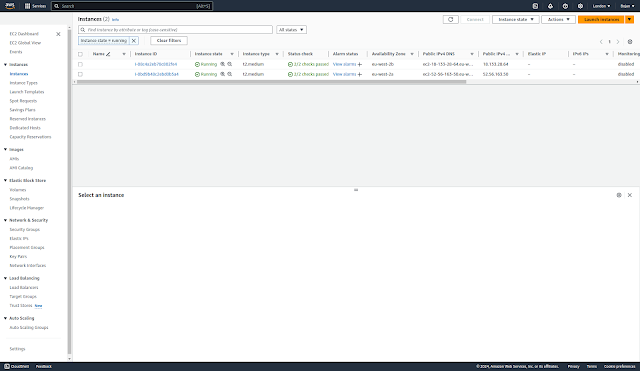
EC2 Instances:


Load balancers:


Listeners:


Network mapping:

Security:


Health checks:


Target instances:


Monitoring:


LB Attributes:


Auto Scaling Groups:


Volumes:


Security Groups:


Testing the deployment 


We saw earlier external IPs for our Voting and Result service which are all behind the load balancer:
  • service/voting-service: aa5334971f30642dea469ec8d3255e35-790812881.eu-west-2.elb.amazonaws.com  
  • service/result-service: aece82f931be943b5a39b5618d5e031e-1908252912.eu-west-2.elb.amazonaws.com 
Let's copy these addresses and use http (port 80) protocol in the browser:

http://aa5334971f30642dea469ec8d3255e35-790812881.eu-west-2.elb.amazonaws.com


If we vote for cats we can see the result here:

http://aece82f931be943b5a39b5618d5e031e-1908252912.eu-west-2.elb.amazonaws.com 


Let's now vote for dogs:


And then check the result:


Destroying Resources


Let's now destroy cost-bearing infra objects.


We'll start with node group:


Let's now destroy cluster:


We can check the progress:


We can also check that all EC2 resources have been destroyed:


WARNING: Make sure Load Balancers created during this exercise are also destroyed. 

More general rule: Delete all deployed Kubernetes services before deleting node groups and clusters.

In my case, Load Balancers were left intact after I performed above described deletion of EKS resources.


If you have active services in your cluster that are associated with a load balancer, you must delete those services before deleting the cluster so that the load balancers are deleted properly. Otherwise, you can have orphaned resources in your VPC that prevent you from being able to delete the VPC.


When you create a Service resource with LoadBalancer as a type, EKS asks the ELB service to create an external load balancer. It depends on how you create a Service, but in the end, the ELB service will create a Classic Load Balancer(CLB) or Network Load Balancer(NLB) for you. If you delete the cluster before deleting the Load Balancers first, they will remain in your account, and you may be charged for them.

Make sure to delete all load balancers created from within Kubernetes.

To find LoadBalancer services:

    kubectl get svc -A | grep LoadBalancer

To delete a service resource:

    kubectl -n NAMESPACE delete svc NAME

This is exactly what I missed to do before I deleted the node group and the cluster.

Prior to cluster destruction I should have deleted all LoadBalancer services:

kubectl destroy -f  ./aws-eks/voting-app-via-deployments/service/voting-app-service-lb.yaml
service/voting-service created

kubectl destroy -f  ./aws-eks/voting-app-via-deployments/service/result-app-service-lb.yaml
service/result-service created

Load Balancers get assigned Public IPv4 address and are chargeable, even if Free Tier is still available.

A configured Load Balancer continues to accrue charges, till you delete it.

Today AWS announced new charges for AWS-provided public IPv4 addresses beginning February 1, 2024.

Types of AWS public IPv4 addresses

1.  Amazon Elastic Compute Cloud (EC2) public IPv4 addresses
When you launch AWS resources in a default Amazon Virtual Private Cloud (VPC), or in subnets that have the auto-assign public IP address setting enabled, they automatically receive public IPv4 addresses from the Amazon pool. 

2.  Elastic IP addresses
An Elastic IP address is a public IPv4 address you can allocate to your AWS account, as opposed to a specific resource.

3. Service managed public IPv4 addresses
AWS managed services that are deployed in your account, such as internet-facing Elastic Load Balancers, NAT gateways, or AWS Global Accelerators, make use of public IPv4 addresses from the Amazon-owned pool. When you deploy managed services in subnets with the auto-assign public IP option enabled, they automatically receive public IPv4 addresses. 

4. BYOIP addresses
There is no charge for using your own IPv4 addresses.

In the updated CUR you will see two new usage types for public IPv4 addresses:
  • PublicIPv4:IdleAddress: shows usage across all public IPv4 addresses that are idle in your AWS account
  • PublicIPv4:InUseAddress: shows usage across all public IPv4 addresses that are in-use by your AWS resources. These include EC2 public IPv4 addresses, Elastic IP addresses, and service managed public IPv4 addresses. It does not include BYOIPs, as there is no charge for using BYOIP addresses.


AWS Free Tier for Amazon EC2 applies to in-use public IPv4 address usage. Usage beyond 750 hours per month of in-use public IPv4 address will be charged at $0.005 per IP per hour as announced in this AWS News blog. 

While there is no additional charge for creating and using an Amazon Virtual Private Cloud (VPC) itself, you can pay for optional VPC capabilities with usage-based charges.

Also see: 

I discovered this resource leak when I was checking my AWS costs:


It was not obvious what exactly in VPC was consuming public IPv4 addresses. VPC on its own and its public subnets (even with Auto-assign IPv4 Address enabled) do not incur any costs. But when I checked EC2 resources, I notices I had those 2 Load Balances created as part of today's exercise up and running. 


$0.005 x 24h x 2 = $0.24

This is exactly daily charge I was having. 

Public IP Insights [View public IP insights - Amazon Virtual Private Cloud], a free feature with in Amazon VPC IP Address Manager (IPAM) also showed that I had some public IP addresses in use:


I've now deleted both Load Balancers: